GETTING
STARTED
 Caution:
The meter has no power-on switch, so it will be in operation as soon as
you apply power.
If
you power off/on the meter, or perform a hard reset (press the RESET
button twice), the meter shows "RST" followed by "STRN".
RATING/PRODUCT
LABEL
This label is located on top of the meter housing.
MAIN BOARD POWER JUMPERS (refer to Figure 3-1)
 Important:
If you want to change the factory preset jumpers, do the following steps,
otherwise go to Section 3.3.
Disconnect the
power from the unit before proceeding.
1.
Remove the main board from the case. Refer to Section 2.6.
2. Locate the solder jumpers W1, W2, and W3 (located near the edge
of the main board alongside the transformer).
3. If your power requirement is 115 V ac, solder jumpers W1 and
W3 should be wired, but jumper W2 should not. If your power requirement
is 230 V ac, solder jumper W2 should be wired, but jumpers W1 and W3
should not.
NOTE: W4 jumper is not used.
Figure 3-1 shows
the location of solder jumpers W1 through W3.
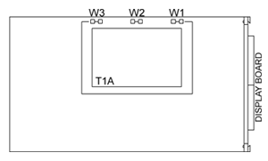
Figure 3-1. Main Board Power Jumpers (W1,
W2, W3)
Figure 3-2 shows the location of jumper positions on the main board.
Figure 3-2.
Main Board Jumper Positions
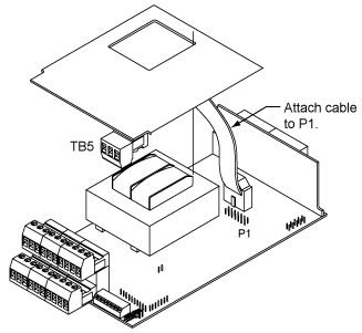
Figure 3-3. Upper Option Board Installation
S2 jumpers are for testing purposes. Do not use as reading errors may
result.
S3 jumpers are used for the following (refer to Table 3-2):
* To enable or disable the front panel push-buttons
* To allow for an extremely low resistance load for analog output
* To disable the MENU button
* To perform calibration procedure
Test pins TP1 - TP11 are for testing purposes. Do not use as reading errors
may result.
S3
Jumper Functions Table
6-1
|
JUMPER
|
DESCRIPTION
|
|
S3-A
|
Install
to enable front panel push-buttons. Remove to disable all front
panel push-buttons
|
|
S3-B
|
Removed.
Install for meter calibration.
|
|
S3-C
|
Normally:
Removed. Install for analog output when load is less than 1 Kohm
impedance. Care should be taken when installing this jumper.
|
|
S3-D
|
Removed. Not used.
|
|
S3-E
|
If installed without S3-B, MENU locks out. If
you press the MENU button, the meter shows "LOCK".
|
PANEL
MOUNTING
1.
Cut
a hole in your panel, as shown in Figure 3-4.For specific dimensions refer
to Figure 3-4.
2. Insert
the meter into the hole. Be sure the front bezel is flush to the panel.
3.
Proceed
to Section 3.4 to connect your sensor input and main power.
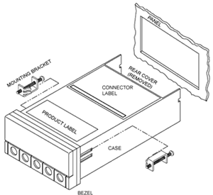
Figure 3-4. Meter - Exploded View
|
Figure
3-5
Panel Cut-Out
|
CONNECTING SENSOR INPUT
Figures 3-5
through 3-11 describe how to connect your sensors.
|
Figure
3-6
3-Wire dc Input Connections with Internal
Excitation
|
Figure
3-7
3-Wire dc Input Connections with External
Excitation
|
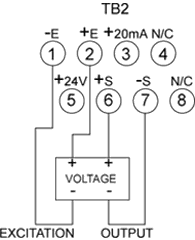 Figure
3-8
4-Wire dc Input Connections with Internal
Excitation
|
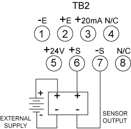 Figure
3-9
4-Wire dc Input Connections with External
Excitation
|
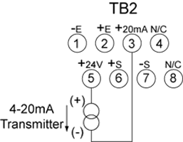 Figure
3-10
DC Current Input Connections with Internal
Excitation
|
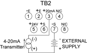 Figure
3-11
DC Current Input Connections with External
Excitation
|
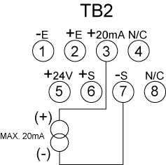
Figure
3-12. DC
Current Input Connections with Current Source
CONNECTING
MAIN POWER
Connect
the ac main power connections as shown in Figure 3-12.
 WARNING:
Do not connect AC power to your meter until you have completed all input
and output connections. Failure to do so may result in injury! WARNING:
Do not connect AC power to your meter until you have completed all input
and output connections. Failure to do so may result in injury!
Connect the DC
main power as shown in Figure 3-13.
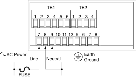 Figure 3-13.
Main Power Connections - AC
AC
Power Connections Table 3-2
|
TB1
|
AC
POWER
|
WIRE
COLORS
|
| |
|
EUROPE
|
USA
|
|
7
|
~
AC Line Black
|
Brown
|
Black
|
|
8
|
~
AC Neutral
|
Blue
|
White
|
|
9
|
~
AC
|
Green/Yellow
|
Green
|
Connect
the ac main power connections as shown in Figure 3-12.
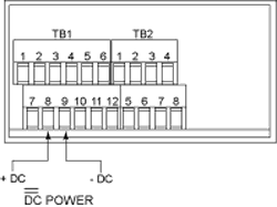
Figure
3-14
Main Power Connections - DC
|
Connect
external tare connections as shown in Figure 3-14.
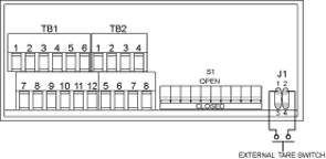
Figure
3-15
External Tare Connections
|
CONNECTING ANALOG AND RELAY
OUTPUT
If you have purchased a meter with analog or dual relay output, refer
to the following drawings for output connections.
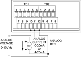
Figure
3-16
Analog Output Connections
|
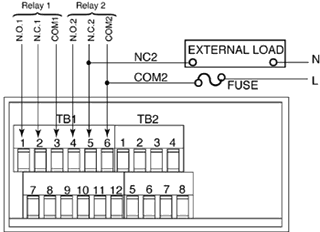 Figure
3-17
Relay Output Connections
|
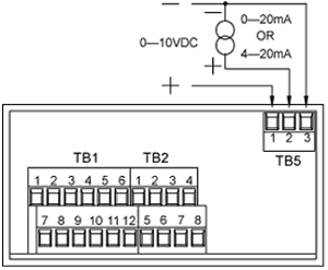
Figure 3-18.
Isolated Analog Output Connections.
|